
What PCCC Is
PCCC, expanded as Programmable Controller Communication Commands, is a command-and-response application protocol defined by Allen-Bradley (now Rockwell Automation) for reading and writing values inside its programmable controllers. Its primary practical advantage is direct, addressable access to the typed file memory model used by the SLC 500, MicroLogix, PLC-5, and legacy ControlLogix data-table compatibility paths, which is still what many older HMI, SCADA, and reporting systems expect to see on the wire.
PCCC is most common in installed Allen-Bradley plants in North American manufacturing, water and wastewater, and process industries. It is rarely chosen for greenfield work today, but it remains the live integration surface in plants where the supervisory layer was built around classic PLC file references and the controller has not been migrated to a tag-based Logix design.
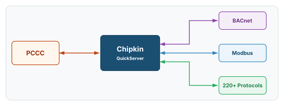
PCCC is a narrower integration path than Modbus or BACnet. Treat new PCCC projects as discovery work first. For field-side issues see the PCCC Troubleshooting Guide.
History
PCCC originated in the early 1980s with Allen-Bradley’s Data Highway and Data Highway Plus networks, where it provided the command set used by HMIs, programming terminals, and supervisory hosts to read PLC memory. It carried forward to serial DF1 in the mid-1980s, was extended for the SLC 500 family in 1991, and survived Rockwell’s transition to CIP and EtherNet/IP by being preserved as an encapsulated object class within those newer protocols.
That history matters because PCCC is rarely a clean modern decision. It is almost always inherited from an installed controller family, an installed HMI database, or an installed driver library that was written before the tag-based Logix model became dominant. Most integration questions are therefore about how to preserve visibility into existing controller files during a longer modernization, not about choosing PCCC for a new design.
Core Concepts
- Command and response. PCCC is a request-driven protocol. A client (HMI, gateway, or programming tool) issues a command; the controller returns data or an acknowledgement. There is no native publish or notify model.
- Typed file addressing. Data is addressed by file type letter, file number, and element offset — for example
N7:0for the first integer in file 7, orT4:0.ACCfor the accumulated value of the first timer in file 4. - Command codes. PCCC defines a fixed set of command codes. Typed File Read (
0x0F/ function0xA2) and Typed File Write (0x0F/0xAA) are the two most-used in integration work; PLC-2/PLC-3/PLC-5 Word Range Read and Write also appear in older systems. - Transports. PCCC has no transport of its own. It runs on DH+, DH-485, DF1 (serial), AB/Ethernet (CSPv4), and EtherNet/IP CIP-encapsulated PCCC (class 0x67). The transport choice determines the framing and address fields, not the PCCC payload.
- Controller family matters. SLC 500, MicroLogix, PLC-5, and the legacy data-table side of ControlLogix all expose PCCC, but their valid file types and element semantics differ. A PCCC client cannot assume one family’s address map will work on another.
- No tag layer. PCCC has no concept of named tags. The address is the file-and-element reference. Tag-based access to a Logix controller is a different protocol (CIP Logix Read Tag service, not PCCC).
PCCC-Specific Information
PCCC integration depends on understanding which controller family is in use, which file types are populated, and which transport is carrying the commands.
Typed File Memory Model
Allen-Bradley controllers organize memory into typed files, each identified by a single-letter prefix and a file number. The element offset within the file is the address used in a PCCC command.
| File Letter | Element Type | Typical Use |
|---|---|---|
O | Output | Discrete and analog outputs |
I | Input | Discrete and analog inputs |
S | Status | Processor status words |
B | Binary (bit) | Single-bit data, addressed as B3:0/0 |
T | Timer | Three-element structures (.PRE, .ACC, control bits) |
C | Counter | Three-element structures (.PRE, .ACC, control bits) |
R | Control | Sequencer and shift-register control |
N | Integer | Signed 16-bit integers |
F | Float | IEEE 754 single-precision |
ST | String | 82-character ASCII strings (SLC/Micro) |
A | ASCII | Two-character-per-word ASCII strings |
L | Long | Signed 32-bit integers (MicroLogix and newer SLCs) |
MG / PD / RI | Message / PID / Routing | Family-specific extended structures |
[!NOTE] The file numbers are conventional, not fixed by the protocol. File 3 is conventionally
B3, file 7 is conventionallyN7, but a programmer can place a binary file at any file number above 9. The XIF-equivalent for PCCC is the controller’s exported program listing, not a hard-coded table.
Command Codes In Daily Use
Most PCCC integration traffic uses a small subset of the command space.
| Command | Function | Purpose |
|---|---|---|
0x0F cmd, 0xA2 func | Protected Typed File Read | Read a range of elements from a typed file |
0x0F cmd, 0xAA func | Protected Typed File Write | Write a range of elements to a typed file |
0x0F cmd, 0xA9 func | Protected Typed Logical Read with 3 address fields | Older typed-read variant still seen on PLC-5 hosts |
0x0F cmd, 0xAB func | Protected Typed Logical Write with mask | Bit-level writes inside a word |
0x06 cmd, 0x03 func | Diagnostic Status | Identifies controller type and firmware |
0x06 cmd, 0x07 func | Diagnostic Counters | Pulls communication counters from the controller |
Diagnostic Status (0x06 / 0x03) is the simplest first test on an unknown PLC because it returns the controller family without requiring any knowledge of the file map.
Transports And Encapsulation
PCCC is a payload, not a transport. Pick the integration approach based on what is actually on the wire.
| Transport | Where It Fits | Notes |
|---|---|---|
| DF1 full-duplex | Direct serial to a single PLC | RS-232 point-to-point; common for legacy programming and HMI links |
| DF1 half-duplex | Multidrop serial to several PLCs | RS-485 with a master/slave structure; less common today |
| AB/Ethernet (CSPv4) | Older Ethernet-attached PLC-5 and SLC 5/05 | Listens on TCP port 2222; predates EtherNet/IP |
| EtherNet/IP with PCCC encapsulation | Modern Ethernet path on legacy controllers | PCCC carried as CIP class 0x67 messages over EtherNet/IP TCP 44818 |
| DH+ / DH-485 via gateway | Plant-floor coax or twisted pair | Almost always reached today through a serial or Ethernet gateway, not directly |
The transport choice changes the diagnostic toolchain. A PCCC-over-EtherNet/IP capture looks like CIP in Wireshark and decodes correctly only when the analyzer understands class 0x67.
Why Two “PCCC” Projects Are Often Different Jobs
Two sites can both describe their integration as “PCCC” while needing different work. Confirm before scoping:
- Is the controller an SLC 500, MicroLogix, PLC-5, or legacy ControlLogix data-table?
- Is the transport DF1 serial, AB/Ethernet, or EtherNet/IP-encapsulated?
- Does the host need a specific command function code, or only a value read?
- Does the integration require writes to controller memory, or only reads?
These four answers together usually determine whether the project is a one-day driver configuration or a multi-week discovery exercise.
Common Variants
| Variant | Where It Fits | Why It Matters |
|---|---|---|
| PCCC over DF1 | Serial point-to-point or multidrop | The most common legacy serial path on installed Allen-Bradley plants |
| PCCC over AB/Ethernet (CSPv4) | Older Ethernet on PLC-5 and SLC 5/05 | Predates EtherNet/IP; uses TCP port 2222 |
| PCCC encapsulated in EtherNet/IP | Modern Ethernet path to legacy controllers | CIP class 0x67; the most common modern PCCC carrier |
Project Startup Questions
PCCC is evidence-constrained at Chipkin. Confirm these gates before quoting configuration time:
- Which controller family is on the network, with firmware revision?
- Which transport is carrying PCCC — DF1, AB/Ethernet, or EtherNet/IP-encapsulated?
- Is the host requirement read-only, or are writes to controller memory expected?
- Is a working file map available from the controller program, or only a list of HMI tag names?
- If the legacy path turns out to be brittle, is a modern fallback (a Logix tag export to Modbus, for example) acceptable to the customer?
A missing answer on any of these is a startup blocker, not a midstream issue.
How To Get The Points List
For PCCC, point lists usually come from the actual PLC file map or a validated list of file and element references the host already uses.
Preferred sources:
- Exported program listing (RSLogix 500, RSLogix 5, or Studio 5000 legacy export) showing file numbers and data types
- Existing HMI or SCADA tag database with the PLC file references in the address field
- Cross-reference report from the engineering tool naming every file element used in logic
- Proven list of file addresses the host already reads in production
The best intake package is the controller family, the exported file map, and clarity about whether a modern fallback path is acceptable if the legacy command route turns out to be brittle.
Devices that Support PCCC
PCCC is implemented natively by the Allen-Bradley controller families that predate or coexist with the Logix tag-based model.
| Family | Typical Use |
|---|---|
| Allen-Bradley PLC-5 | Plant-floor process and discrete control, mid-1980s to mid-2000s |
| Allen-Bradley SLC 500 (SLC 5/01 through 5/05) | Mid-tier plant control |
| Allen-Bradley MicroLogix 1000 / 1100 / 1200 / 1400 / 1500 | Small-machine and OEM control |
| Allen-Bradley ControlLogix legacy data-table | PCCC compatibility surface on early Logix controllers |
| Third-party PCCC gateways and drivers | Used when a host needs PCCC semantics against a non-Rockwell controller or for protocol bridging |
Common Integration Targets
- BACnet for supervisory visibility of controller data in building-adjacent process plants
- Modbus for register-based monitoring and SCADA interoperability
- EtherNet/IP when the supervisory layer is already CIP-aware
- MQTT for cloud telemetry off legacy controller files
Tools & Diagnostics
| Tool | Type | Description |
|---|---|---|
| QuickServer | Chipkin protocol gateway | Reads PCCC over DF1, AB/Ethernet, or EtherNet/IP encapsulation and exposes data to BACnet, Modbus, MQTT, and 220-plus downstream protocols |
| FieldServer Toolbox | Chipkin diagnostics | Verifies gateway exposure and connectivity once PCCC mapping is in place |
| RSLogix 500 / RSLogix 5 / Studio 5000 | Rockwell engineering software | Authoritative tool for confirming controller family, file structure, and data types |
| Wireshark | Packet capture | Decodes DF1 over serial (with a serial-tap setup) and PCCC inside EtherNet/IP class 0x67 messages |
| Legacy HMI or SCADA exports | Intake artifact | Proves which file addresses are actually used in production |
Frequently Asked Questions
How is PCCC different from CIP tag reads on a Logix controller?
PCCC uses typed file addressing (N7:0, B3:0/0, T4:0.ACC); CIP tag reads use symbolic tag names against the Logix tag database. They are different protocols. A ControlLogix controller can expose both, but only because Rockwell preserved a PCCC compatibility surface alongside the native tag model.
Why does PCCC sometimes appear inside EtherNet/IP traffic?
Rockwell preserved PCCC as an encapsulated object class (class 0x67) so that hosts written against the legacy command set could keep working when the network moved from DH+ or DF1 to Ethernet. The PCCC payload is the same; only the framing changed.
What file addresses does a typical PCCC integration touch?
Most integration work touches N (integer), F (float), B (bit), and the T/C control structures. Output and input files (O and I) are usually exposed to HMIs but rewritten through ladder logic rather than direct PCCC writes from outside.
Is PCCC a good choice for new designs?
Usually no. New Allen-Bradley designs use the Logix tag model with CIP. PCCC is integration-only — relevant because installed controllers still expose it and installed hosts still expect it.
Can a PCCC client write directly to controller memory?
Yes, with the Protected Typed File Write command (0x0F / 0xAA) or the masked-write variant (0x0F / 0xAB). Writes to output files and status files are constrained by the controller’s protection settings and should be agreed with the controls team before being enabled in a gateway.
Reference Documents
- Rockwell Automation DF1 Protocol and Command Set Reference Manual (1770-RM516) — authoritative reference for the PCCC command set, function codes, and DF1 transport framing.
- Rockwell Automation EtherNet/IP Embedded Object Library — vendor documentation for the EtherNet/IP CIP class 0x67 PCCC encapsulation.
- ODVA EtherNet/IP — standards body for EtherNet/IP, the modern PCCC carrier.
- Wikipedia: Allen-Bradley PCCC — useful overview for terminology and history within the broader CIP family.